 English
 Українська
 Русский
Auditory brainstem responses (ABRs) recorded from electrodes placed on the scalp represent far field potentials generated by the fiber tracts and nuclei of the ascending auditory pathway between the cochlea and the brainstem.
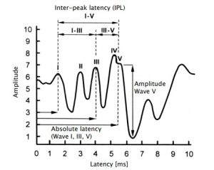
Figure 1: Overview of ABR waves
ABR can be elicited with several stimuli as e.g. clicks, chirps or tone bursts. Broadband stimuli as click and broadband chirp are temporally concise stimuli which result in synchronized neural discharges and robust potentials. They are used to stimulate as many as possible sensory cells along the cochlea for getting highest neural activity on the nerve fibers. However, temporal specificity of the stimulus is achieved at the expense of frequency specificity. In contrast, narrowband stimuli as frequencyspecific chirp or tone burst comprise limited frequency components. Sensory cells are stimulated at the site within the cochlea corresponding to the stimulus frequency components. Due to the travelling time along the basilar membrane latency varies, i.e. it increases with decreasing frequency.
Typically, with decreasing frequency also the amplitude decreases and the waveform gets less sharply defined. With increasing stimulus level the frequency specificity decreases due to an increasing spread of excitation.
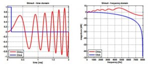
Figure 2: ABR stimuli: click and chirp (left: time domain; right: frequency domain)
PRACTICAL USE
Select ABR from the module selection screen. If more than one AEP test is licensed, ABR can be found in the AEP section. Select the preset that you would like to perform. If necessary, change the parameters (e.g. stimulus type, stimulus polarity, contralateral masking noise, stimulus level, stimulus rate, number of averages, noise stop criterion, Spread Spectrum, Auto Proceed, Auto Stop, age group for normative latency areas) and the preset name as required.
The different parameter options and possible applications are explained in the following:
Stimulus type:
– Click at low stimulus rates (≤ 20 Hz) evokes clear waves I, III, and V and can be used to obtain information on amplitude and latency. Use click for neurological issues, where the evaluation of inter-peak latency is required. Due to poor frequency specificity thresholds can be assessed only qualitatively. For hearing screening click-ABR measurements are conducted by using a fixed screening level (e.g. 35 dB nHL).
– Chirp evokes higher response amplitudes than click for wave III and V. In contrast, wave I is typically hard to identify. Use chirps for hearing threshold determination, because only wave V is evaluated.
– Narrowband (low-, mid-, high-) chirps provide latency information and are more frequencyspecific than broadband stimuli (click, broadband chirp). Hence, they may be used for a more frequency-specific hearing threshold determination. However, the response amplitude is typically lower than for broadband stimuli, so that the response is harder to detect in the time domain. Please note that for low- and mid-chirps ipsilateral masking noise is presented in order to reduce response contributions from more basal cochlear regions.
– Tone bursts are more frequency-specific than narrow-band chirps but yield lower amplitudes (especially at lower levels).
Stimulus polarity:
– Alternating polarity helps reduce the stimulus artefact that is generated by the transducer itself (especially recommended for bone conduction measurements). Alternating polarity provides a broader, rounded wave V peak.
– Rarefaction and condensation provides a more peaked response and may yield higher amplitude for wave I. Latency difference between condensation and rarefaction is nearly identical in normal hearing adults. However, responses to condensation and rarefaction clicks may considerably differ in patients with cochlear hearing loss.
Rate Mode:
– If activated, the test can be performed for a fixed stimulus level at multiple stimulus rates.
Masking noise:
– Contralateral masking is recommended if there is significant asymmetry in hearing loss between ears, i.e. for differences of about 30 to 40 dB (headphones) or 50 to 60 dB (insert earphones). If a bone conductor is used, application of contralateral noise is essential.
Stimulus level:
Up to eight stimulus levels (including repetitions) can be pre-configured. Stimulus levels are given in dB nHL, i.e. relative to the hearing threshold of a collective of normal hearing subjects, which is defined as 0 dB nHL. A stimulus level can be repeated up to three times. A mute stimulus is available for comparative measurements. Measurements start at the highest level. The standard deviation of latency is typically lower and wave amplitude is higher at higher stimulus levels. At lower stimulus levels, wave I (at about 60 dB nHL) and wave III (at about 30 dB nHL) disappear. In rate mode only one stimulus level can be set.
Stimulus rate:
The higher the stimulus rate, the smaller the response amplitude (notably for I to IV and for high levels) and the longer the latency. The latency shift due to stimulus rate is compensated on the device and hence not visible in the result graph. Higher rates improve efficiency of data collection by reducing measurement time at a fixed number of averages, but jeopardize the identification of a response, particularly in some pathological cases. Wave I and III may
disappear at stimulus rates above 50 Hz. If all waves are intended to be evaluated (e.g. for neurological diagnostics) low stimulus rates should be used. For ABR threshold determination also higher stimulus rates may be used. 50 and 60 Hz are not available stimulus rates because these are typical power system frequencies. By pressing the stimulus rate box, a user-defined stimulus rate can be entered. The resulting inter-stimulus interval is displayed on the settings screen. In rate mode up to eight stimulus rates (including repetitions) can be selected.
Number of averages:
At fixed measurement conditions, with increasing number of averages, the noise floor decreases (number of averages increased by factor four reduces noise by half), but the measurement time increases. The time per trace and the total measurement time are shown on the settings screen.
Spread Spectrum:
If activated, the stimulus rate is slightly varied in order to reduce the influence of electrical interference synchronized to the stimulus rate. Also, ABR amplitude is known to decrease at a constant stimulus rate due to adaptation. Activation of this option is always recommended. Please note that the Spread Spectrum option is always active for stimulus rates exceeding 70 Hz and during binaural stimulation for decoupling the responses from the two channels.
Automated Wave V detection:
If activated, the occurrence of a statistically valid wave V is automatically detected.
Minimum Wave V amplitude:
If Automated Wave V detection is activated, the minimum wave V amplitude, which must be available to mark a recognized wave V as valid, can be selected.
Auto Proceed:
If activated, the recording of a trace is stopped as soon as a statistically valid wave V is detected for the given trace. The test then proceeds with the recording of the next trace.
Please note that this option is only available if the automated wave V detection option is activated.
Auto Stop:
If activated, the test stops if for two consecutive traces no statistically valid wave V could be detected. Please note that this option is only available if the automated wave V detection option is activated.
Noise stop criterion:
If activated (i.e. noise stop criterion >0 nV), the recording of a trace is stopped as soon as the residual noise drops below the defined noise threshold and no response is detected. Hence, if activated this option speeds up the recording in case no response is present.
Age group (for normative latencies):
Select the appropriate age group corresponding to the age of the tested subject. Before the test is started the subject should be instructed about the test procedure. In order to reduce muscle artefacts, the subject should be calm and fully relaxed lying comfortably on a recliner Page 93 / 140 or bed. It is also recommended that subjects keep their eyes closed during the measurement for reducing artefacts e.g. due to eye blinks. For babies, try to test the subject during sleep. In order to reduce environmental artefacts, conduct the measurement in a room with low electromagnetic radiation, i.e. in an electrically shielded metal booth or any other room without powered-on electric
devices (e.g. computer, light, telephone, cell phone, power transformer) in close range to the measurement equipment. An acoustically shielded booth or a quiet room is recommended if ABR is applied for threshold determination at low sound pressure levels.
Make sure that a valid transducer (e.g. headphone, insert earphone, ear probe, bone conductor) and electrode cable are connected. Make sure that the skin is clean at the intended positions of the electrodes. If applicable, thoroughly clean the skin (e.g. using skin prepping gel) in order to remove dirt, oil, and superficial dead skin. Select appropriate electrodes and attach them on the skin of the patient. An electrolyte gel may be put on the electrode contact in order to improve the conductivity of the skin layer, which effectively increases the electrode surface area. Attach the electrode clips of the electrode cable at the correct electrode. The white and red electrode are the recording electrodes, the black electrode is the ground electrode. Do not place the ground electrode near the heart to avoid inducing electrocardiography (ECG) waves. There are several possibilities to place the electrodes. The position of the electrodes affects waveform morphology and latency. Best electrode position for yielding maximum wave amplitudes is vertex (white electrode) and ipsilateral mastoid (red electrode).
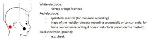
Figure 3: ABR electrode positioning with vertical montage
When performing an ABR test with an ear probe, information about ear probe calibration ① and impedance measurement ② are shown on screen (see Figure 48). You can configure the ear probe calibration view mode in AEP Preferences to Simple or Expert mode. If the results from impedance measurement or ear probe calibration are not fully valid, a forward button may occur in order to proceed to the ABR test.
After successful electrode impedance measurement, you can start the test by pressing the play (or forward) button. The ABR stimulus is presented via the transducer and the response is detected via the electrode cable. During the measurement the electrode impedance is monitored. In case that impedances get too high (e.g. an electrode has fallen off), the test is automatically interrupted.
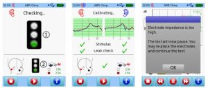
Figure 4: ABR impedance measurement and ear probe calibration (left: good impedances and ear probe fit (simple mode); middle: good impedances and ear probe fit (binaural test, expert mode; right: bad impedance during measurement)